Simulated Production Environment Today |
Evaluation of the numerical process simulation of selective laser melting
| Journal | Industry 4.0 Science |
| Issue | Volume 40, 2024, Edition 4, Pages 70-77 |
| Open Access | https://doi.org/10.30844/I4SE.24.4.70 |
| Bibliography | Share | Cite | Download |
Abstract
Keywords
Article
Additive Manufacturing
There are mainly two additive manufacturing processes for metals: powder bed fusion (PBF) and directed energy deposition (DED). In both processes, the desired component is produced layer by layer. In PBF, a powder bed is first spread across the work area, which is then melted locally by a heat source. The build platform is lowered and the process is repeated for subsequent layers. In DED, the feedstock material in powder or wire form is melted and consolidated by a focused heat source during deposition [1]. The resulting component properties depend heavily on the selected process parameters. For laser-based powder bed fusion (L-PBF) processes, which are the focus of this article, 130 factors were identified. Figure 1 visualizes the main influencing parameters [2].
Challenges in the numerical simulation of AM include high temperature gradients, material non-linearities, complex geometries, multiple scales and physical couplings [3]. Together, this means that the simulation must have a very high resolution compared to part dimensions in the centimeter range and build times of several hours. In [4] a melt pool depth of 84 μm and a melt lifetime of approx. 700 μs were simulated.
Classification of simulation methods
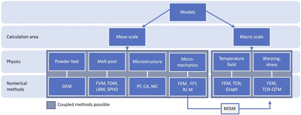
Different mathematical models and numerical methods are used depending on the object under investigation. Figure 2 provides an overview of the methods mentioned in this work. A quantitative prediction of the macroscopic properties of additively manufactured parts requires the simulation of all mechanisms that are relevant for the formation of the microstructure, defects (e.g. pores) and thermal stresses. Due to the complexity of the interactions between the physical processes taking place, it isn’t easy to represent them within a single mathematical model [5].
Depending on the size of the computational domain, the models currently used are divided into high-resolution mesoscopic simulations and macroscopic part scale simulations. At the mesoscopic level, thermo-fluid [6], thermo-microstructural [7] and thermo-mechanical models [8] are established, each highlighting different aspects of the process. At the part scale, a distinction can be made between thermal, mechanical and thermo-mechanically coupled models.
A quantitative prediction of the macroscopic properties of additively manufactured parts requires the simulation of all mechanisms that are relevant for the formation of the microstructure, defects (e.g. pores) and thermal stresses. Due to the complexity of the interactions between the physical processes taking place, it isn’t easy to represent them within a single mathematical model [5]. Depending on the size of the computational domain, the models currently used are divided into high-resolution mesoscopic simulations and macroscopic part scale simulations. At the mesoscopic level, thermo-fluid [6], thermo-microstructural [7] and thermo-mechanical models [8] are established, each highlighting different aspects of the process. At the part scale, a distinction can be made between thermal, mechanical and thermo-mechanically coupled models. The various models are briefly presented below.

Powder bed
Powder application is usually simulated using the discrete element method (DEM). For this purpose, the powder particles are usually assumed to be soft spheres. In this context, “soft” means that a small overlap of the powder particles is allowed, whereby (visco-)elastic and plastic deformations during contact can be considered. The assumption of the spherical shape not only simplifies the underlying Newton-Euler equations, which describe the rigid body dynamics [9], but also makes physical sense due to the better flow properties compared to irregularly shaped powder [10]. The flow properties affect, among other things, the homogeneity and packing density of the powder bed [10]. Particle geometries that deviate from the optimal spherical shape can be approximated as a superposition of spheres [11].
Further possibilities are described in [12]. A very common simplification is the generation of the powder bed by free fall of a particle cloud [13]. However, a more realistic modeling of the powder spreading process with recoater blades makes it possible to capture the influence of some process parameters, such as blade velocity and layer thickness, on the generated powder bed and thus on the generated layer [14]. The stochastic distribution of powder can significantly influence the simulated surface roughness [13].
Melt pool
The simulation of the melt pool is based on Computational Fluid-Dynamics (CFD). In addition to the conductive energy transport in thermal models, the convective mass, momentum and energy transport is also considered. Finite volume (FVM) [15], finite difference (FDM) [4], Lattice-Boltzmann (LBM) [16] or smoothed particle hydrodynamics (SPHD) [17] can be used to solve the (incompressible) Navier-Stokes equations. The dynamics in the melt pool are dominated by thermo-capillary forces and evaporation pressure [13]. The ability to handle free surfaces and phase transformations is therefore an integral part of current models.
These models allow the investigation of defects such as pores, balling or lack-offusion [6]. Furthermore, the powder bed can be completely resolved on the mesoscopic scale instead of assuming homogenized powder properties. Some effects such as the fragmentation of the melt pool are not only influenced by instabilities (Rayleigh plateau instability), but are also strongly dependent on the stochastic powder distribution [13]. In principle, the numerical effort limits the simulations to a few tracks and layers [18].
Microstructure
The (thermo-)microstructural models can be used to predict phase transformations [19], grain size distribution and orientation [20], as well as the formation of dendrites and segregation [21]. The temperature field is applied as an external load and can be determined analytically [7] or numerically [8]. Once the temperature field is known, it is possible to calculate solidification from the melt using phase field models (PF), cellular automata (CA) or Monte Carlo Potts models (MC) [7].
The different models are discussed in detail in [22]. The PF models are able to describe the growth of dendrites and segregations of alloying elements—in this form, however, they can only be applied to computational domains in the micrometer range. Adapted models enable the calculation of grain size distributions and grain orientations, which can be calculated more efficiently with CA [9].
Furthermore, phenomenological approaches were used to determine phase transformations. For this purpose, the Koistinen- Marburger law for diffusionless phase transformations and the Johnson-Mehl-Avrami-Kolmogorov equation (JMAK) for diffusion-driven phase transformations were used by [5] for PBF-LB with Ti6Al4V powder. An approach for the calculation of phase transformations in arbitrary metal alloys was developed by [19].
Micromechanics
An important task of micromechanics is the linking of mechanical relationships on different scales [23]. A detailed thermo-mechanical analysis was used by [24] to identify inherent strains for a subsequent, purely mechanical part scale simulation (see following chapter). An elasto-plastic material model (e.g. J2 -plasticity) is usually used for this purpose [25]. It is also possible to derive apparent mechanical properties from a representative volume element (RVE) using computational homogenization (CH). [26] take this RVE from the simulation domain of their microstructure simulation. Various homogenization methods are compared in [27], focusing on the numerical effort and applicability to polycrystalline microstructures.
Of the six methods discussed, the spectral methods based on the Fast Fourier Transform (FFT) are particularly suitable for the homogenization of RVE with periodic boundary conditions. However, these approaches are not capable of capturing macroscopic influences that affect local solidification conditions and thus lead to spatially inhomogeneous properties. This may be due to the geometry of the component or the distance to the build platform.
Part scale simulation
Various macroscopic approaches have been developed to enable the simulation of entire parts with acceptable numerical effort. Since the thermal energy input directly or indirectly influences process-relevant phenomena such as phase transformation, thermal distortion and residual stresses [2], thermal and thermomechanical models are often used. The thermal analyses are based on the solution of the heat conduction equation with suitable boundary conditions. In order to model the material deposition, the individual layers are activated one by one during the simulation.
Common simplifications include (1) combining several layers into one superlayer (2) replacing the local heat source with an equivalent volumetric heat source 3) and homogenized properties of supports [28]. In addition, the powder properties are homogenized. The element size is only limited by the size of the superlayer, which enables an efficient numerical solution [13].
Since a thermomechanical analysis is still computationally expensive, purely mechanical approaches such as the inherent strain method (ISM) have also been developed for distortion prediction [29]. The inherent strains can be determined analytically, numerically or experimentally [18]. In the modified inherent strain method (MISM), the inherent strains are determined by means of a thermomechanical analysis at the mesoscale and transferred layer by layer to the entire part in a quasi-static analysis [18]. The MISM was used to optimize support structures, part orientation and scan path, among other things [18].
The analyses are often carried out using FEM. In addition, promising alternative approaches are emerging. Yavari et al [30] use a graph-theoretical approach. The authors simulated the temperature history in a large volume impeller in 17 minutes. This can be compared to an FEM simulation with a runtime of 4.5 h and the actual build time of 16 h. The relative deviation of the simulated temperature history in relation to experimental data is approximately 9 %. This also shows that despite the simplifications in the thermal model, there is still good Ababgre.e 3ment with experimental observations.
Peng et al. [28] use a so-called Thermal Circuit Network (TCN) as a substitute model. According to the authors, their model is 100 times faster than classical FEM-based approaches. For a component in a flat and upright position, the runtimes were 2 min (flat) and 19 min (upright) compared to FEA with 14 h (flat) and 41 h (upright), with a relative deviation of the results of less than 15 %. The authors combine this with a quasi-static thermo-mechanical model (TCN-QTM) to calculate thermal stresses [25].
Multiphysical coupling
The large number of models illustrates the complexity of a comprehensive process simulation. In most cases, the coupled multi-physical problem is divided into subproblems, which can be analyzed sequentially. This approach is particularly suitable for weakly coupled problems.
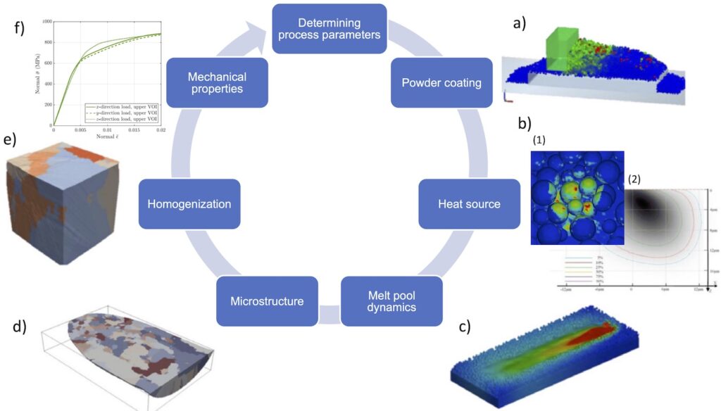
For example, the energy equation and the momentum equation in thermo-mechanical models are often assumed to be weakly coupled, since thermal energy much larger than mechanical energy [31]. There is great interest in integrating these subproblems into a single framework [26]. One possible concept is presented by [26] for PBFEB (also known as electron beam melting, or EBM for short) (Fig. 3).
The electron beam is modeled as a volumetric heat source. The spatial absorption rate is calculated by MC simulation of the electron paths (Fig. 3.b (2)). In contrast, the interaction length of the laser is only a few nanometers, which is why the heat source in PBF-LB is modeled as a surface heat source [13]. The multiple reflections of the laser beam on free surfaces are modeled by ray tracing [32] (Fig. 3.b (1)). The powder distribution for the subsequent CFD simulation was calculated using DEM (Fig. 3.a).
To calculate the thermal stresses, the temperature field is transferred to an FE solver on already solidified control volumes (FV). This enables the coupling of the CFD simulation (Fig. 3.c) with a thermomechanical simulation. Furthermore, the calculated temperature fields serve as input for the CA model for microstructure simulation (Fig. 3.d).
Subsequently, a special reducedorder method (ROM), called self-consistent clustering analysis (SCA) by the authors, is used to derive local mechanical properties from the calculated microstructure (Fig. 3.e-f). [5] describes a way of deriving the dependence of undercooling of the melt on the solidification rate of the dendrites from a PF simulation. This allows the thermodynamics in CA to be placed on a solid physical basis. It is also possible to enrich the microstructure simulation by calculating phase transformations [19].
Conclusion
The simulation of PBF-LB currently holds great research potential due to the large number of influencing factors. This article provides an overview of common physics-based approaches. Different methods to investigate individual aspects of the process such as powder deposition, melt pool dynamics, microstructure and thermal distortion were presented. However, the exchange of information between different time and space scales is still a major hurdle. Computational homogenization and the inherent strain method are commonly used to bridge scales.
Moreover, models are often assumed to be weakly coupled (e.g. DEM-CFD [15] or CFD-CA [20]). Substitute models such as TCN or more efficient algorithms (GPU computing) can help to speed up simulations. Inverse solution strategies, in which, for example, the required process parameters to achieve a desired property profile could be found using data-driven approaches, were not considered in this overview. Some approaches for optimizing process parameters and for optimizing topology or material properties are discussed in [13].
Bibliography
[1] DIN EN ISO/ASTM 52900:2022-03. In: Additive Fertigung_- Grundlagen_- Terminologie (ISO/ASTM 52900:2021). Deutsche Fassung EN_ISO/ASTM 52900:2021. Berlin 2022. DOI: 10.31030/3290011.[2] Wang, D.; Yang, Y.; Liu, Y.; Bai, Y.; Tan, C.: Factors Affecting the Manufacturing Quality of Laser Powder Bed Fusion in Laser Powder Bed Fusion of Additive Manufacturing Technology. In: Additive Manufacturing Technology (2024), pp. 35-58. DOI: 10.1007/978-981-99-5513-8_2.
[3] Kollmannsberger, S.; Özcan, M.; Carraturo, N., Zander, N.; Rank, E.: A hierarchical computational model for moving thermal loads and phase changes with applications to selective laser melting, Computers & Mathematics with Applications 75 (2018) 5, pp. 1483-1497. DOI: 10.1016/j.camwa.2017.11.014.
[4] Lee, Y. S.; Zhang, W.: Modeling of heat transfer, fluid flow and solidification microstructure of nickel-base superalloy fabricated by laser powder bed fusion. In: Additive Manufacturing 12 (2016), pp. 178-188. DOI: 10.1016/j.addma.2016.05.003.
[5] Higgins, D.: Investigating the Microstructure Evolution of Additive Manufactured Parts using Multiscale Modeling. July 2023.
[6] Sun, Z.; Chueh, Y.-H.; Li, L.: Multiphase mesoscopic simulation of multiple and functionally gradient materials laser powder bed fusion additive manufacturing processes. In: Additive Manufacturing 35 (2020). DOI: 10.1016/j.addma.2020.101448.
[7] Pauza, J. G.; Tayon, W. A.; Rollett, A. D.: Computer simulation of microstructure development in powder-bed additive manufacturing with crystallographic texture, Modelling Simul. Mater. Sci. Eng, 29 (2021) 5, 055019. DOI: 10.1088/1361-651X/ac03a6.
[8] Chen, F.; Yan, W.: High-fidelity modeling of thermal stress for additive manufacturing by linking thermal-fluid and mechanical models. In: Materials & Design 196 (2020), 109185. DOI: 10.1016/j.matdes.2020.109185.
[9] De Lorenzis, L.; Düster, A. (Eds.): Modeling in Engineering Using Innovative Numerical Methods for Solids and Fluids. In: CISM International Centre for Mechanical Sciences 599 (2020) . DOI: 10.1007/978-3-030-37518-8.
[10] Herzog, D.; Seyda, V.; Wycisk, E.; Emmelmann, C.: Additive manufacturing of metals, Acta Materialia 117 (2016), pp. 371-392. DOI: 10.1016/j.actamat.2016.07.019.
[11] Nan, W.; Ghadiri, M.: Numerical simulation of powder flow during spreading in additive manufacturing. In: Powder Technology 342 (2019), pp. 801-807. DOI: 10.1016/j.powtec.2018.10.056.
[12] Dong, K.; Wang, C.; Yu, A.: A novel method based on orientation discretization for discrete element modeling of non-spherical particles. In: Chemical Engineering Science 126 (2015), pp. 500-516. DOI: 10.1016/j.ces.2014.12.059.
[13] Markl, M.; Körner, C.: Multiscale Modeling of Powder Bed-Based Additive Manufacturing. In: Annu. Rev. Mater. Res. 46 (2016) 1, pp. 93-123. DOI: 10.1146/annurev-matsci-070115-032158.
[14] Mussatto, A.; Groarke, R.; O’Neill, A.; Obeidi, M. A.; Delaure, Y.; Brabazon, D.: Influences of powder morphology and spreading parameters on the powder bed topography uniformity in powder bed fusion metal additive manufacturing. In: Additive Manufacturing 38 (2021), 101807. DOI: 10.1016/j.addma.2020.101807.
[15] Li, E.; Zhou, Z.; Wang, L.; Zou, R.; Yu, A.: Modeling of keyhole dynamics and melt pool flow in laser powder bed fusion process. In: Powder Technology 400 (2022), 117262. DOI: 10.1016/j.powtec.2022.117262.
[16] Körner, C.; Attar, E.; Heinl, P.: Mesoscopic simulation of selective beam melting processes. In: Journal of Materials Processing Technology, 211 (2011) 6, pp. 978-987. DOI: 10.1016/j. jmatprotec.2010.12.016.
[17] Ma, Y.; Zhou, X.; Zhang, F.; Weißenfels, C.; Liu, M.: A novel smoothed particle hydrodynamics method for multi-physics simulation of laser powder bed fusion. In: Comput Mech. (2024). DOI: 10.1007/s00466-024-02465-5.
[18] Bayat,M.;Dong,W.;Thorborg,J.;To,A.C.;Hattel,J.H.Areview of multi-scale and multi-physics simulations of metal additive manufacturing processes with focus on modeling strategies. In: Additive Manufacturing 47 (2021), 102278. DOI: 10.1016/j.addma.2021.102278.
[19] Zhang,Q.;Xie,J.;Gao,Z.;London,T.;Griffiths,D.;Oancea,V.:A metallurgical phase transformation framework applied to SLM additive manufacturing processes. In: Materials & Design 166 (2019), 107618. DOI: 10.1016/j.matdes.2019.107618.
[20] Lian,Y.;Gan,Z.;Yu,C.;Kats,D.;Liu,W.K.;Wagner,G.J.:Acellular automaton finite volume method for microstructure evolution during additive manufacturing. In: Materials & Design 169 (2019), 107672. DOI: 10.1016/j.matdes.2019.107672.
[21] Azizi,H.;Ebrahimi,A.;Ofori-Opoku,N.;Greenwood,M.Provatas, N.; Mohammadi, M.: Characterizing the microstructural effect of build direction during solidification of laser-powder bed fusion of Al-Si alloys in the dilute limit: A phase-field study. In: Acta Materialia 214 (2021), 116983. DOI: 10.1016/j. actamat.2021.116983.
[22] Körner,C.;Markl,M.;Koepf,J.A.:ModelingandSimulationof Microstructure Evolution for Additive Manufacturing of Metals: A Critical Review. In: Metall Mater Trans A 51 (2020) 10, pp. 4970-4983. DOI: 10.1007/s11661-020-05946-3.
[23] Gross, D.; Seelig, T.: Bruchmechanik. Berlin Heidelberg 2016. DOI: 10.1007/978-3-662-46737-4.
[24] Chen,Q.;Liang,X.;Hayduke,D.;Liu,J.;Cheng,L.:Aninherent strain based multiscale modeling framework for simulating part-scale residual deformation for direct metal laser sintering. In: Additive Manufacturing 28 (2019), pp. 406-418. DOI: 10.1016/j.addma.2019.05.021.
[25] Peng,H.;Ghasri-Khouzani,M.;Gong,S.;Attardo,R.,Ostiguy,P; Rogge, R. B.; Gasterell, B.A.; Budzinski, J.; Tomono, C.; Neidig, J.; Shankar, M. R.; Billo, R.; Go, D.B. Hoelzle, D.: Fast prediction of thermal distortion in metal powder bed fusion additive manufacturing: Part 2, a quasi-static thermo-mechanical model. In: Additive Manufacturing 22 (2018), pp. 869-882. DOI: 10.1016/j. addma.2018.05.001.
[26] Yan, W.; Lian, Y.; Kafka, O. L.; Liu, Z.; Liu, W. K.: An integrated process –structure–property modeling framework for additive manufacturing. In: Computer Methods in Applied Mechanics and Engineering 339 (2018), pp. 184-204. DOI: 10.1016/j. cma.2018.05.004.
[27] March,N.G.;Gunasegaram,D.R.;Murphy,A.B.:Evaluationof computational homogenization methods for the prediction of mechanical properties of additively manufactured metal parts. In: Additive Manufacturing 64 (2023), 103415. DOI: 10.1016/j. addma.2023.103415.
[28] Peng,H.;Ghasri-Khouzani,M.;Gong,S.;Attardo,R.,Ostiguy,P; Rogge, R. B.; Gasterell, B. A.; Budzinski, J.; Tomono, C.; Neidig, J.; Shankar, M. R.; Billo, R.; Go, D. B. Hoelzle, D.: Fast prediction of thermal distortion in metal powder bed fusion additive manufacturing: Part 1, a thermal circuit network model. In: Additive Manufacturing 22 (2018), pp. 852-868. DOI: 10.1016/j. addma.2018.05.023.
[29] Mohammadtaheri,H.;Sedaghati,R.;Molavi-Zarandi,M.Inherent strain approach to estimate residual stress and deformation in the laser powder bed fusion process for metal additive manufacturing—a state-of-the-art review. In: Int J Adv Manuf Technol 122 (2022) 5-6, pp. 2187-2202. DOI: 10.1007/s00170- 022-10052-2.
[30] Yavari R.; Williams, R.; Riensche, A.; Hooper, P.A.; Cole, K. D.; Jaquemetton, L.; Halliday, H. S.; Rao, P.K.: Thermal modeling in metal additive manufacturing using graph theory — Application to laser powder bed fusion of a large volume impeller. In: Additive Manufacturing 41 (2021), 101956. DOI: 10.1016/j. addma.2021.101956.
[31] Denlinger, E. R.; Gouge, M.; Irwin, J.; Michaleris, P.: Thermomechanical model development and in situ experimental validation of the Laser Powder-Bed Fusion process. In: Additive Manufacturing 16 (2017), pp. 73-80. DOI: 10.1016/j. addma.2017.05.001.
[32] Huang,W.;Wang,H.;Rinker,T.;Tan,W.:Investigationofmetal mixing in laser keyhole welding of dissimilar metals. In: Materials & Design 195 (2020), 109056. DOI: 10.1016/j.matdes.2020.109056.