Adaptive In-Orbit Servicing of Altered Satellite Components |
Adaptive gripper placement on altered components for servicing in-orbit satellites

| Journal | Industry 4.0 Science |
| Issue | Volume 41, 2025, Edition 6, Pages 10-21 |
| Open Access | https://doi.org/10.30844/I4SE.25.6.10 |
| Bibliography | Share | Cite | Download |
Abstract
Keywords
Article
Given the concept of “New Space” and the associated developments in commercialization and privatization, space travel is entering a new era. This latest era is characterized by new mega-constellations such as OneWeb, Starlink, Kuiper, and Guowang and which are leading to a significant increase in the number of satellites in orbit [1]. The increase in satellites is resulting in serious problems such as space debris. In its annual “Space Environment Report 2025” [2], the ESA put the increased number of objects tracked at almost 40,000. A particular problem arises with satellites that have spun out of control and cannot return to orbit.
This situation is exacerbated by the lack of in-orbit servicing capabilities. New concepts such as the in-orbit factory [3] offer alternative solutions. In the long term, it seems sensible to minimize the costs incurred and resources used in the satellite sector by considering the possibility of direct maintenance or repairing defective satellites in orbit. This could lead to an extension of the active service life of individual satellites and a reduction in the need for new satellites. Instead of using complete satellites, significantly lighter spare parts as raw materials could be sent directly to an in-orbit factory, which does automated in-orbit servicing. This would be a sustainable way of reducing costs and space debris.
However, it should be noted that in-orbit servicing presents several challenges. External influences during rocket launch and the operational phase in orbit (collisions with asteroids, space debris, or other active satellites) can alter the physical structure of satellites. In some cases, existing (dis)assembly steps can no longer be carried out as planned because the gripping surfaces are no longer available or the component inertia and/or dynamics have changed significantly. Thus, an adaptive method is needed to identify gripping surfaces on the components. This is essential to ensure automated maintenance of the satellites in changed conditions.
State of the art for in-orbit servicing
In-orbit servicing needs to be solved first to reduce both space debris and the high costs of launching satellites. The main objectives of in-orbit servicing can be divided into life extension/station keeping, refuelling, de/re-orbiting, salvage & recycling, relocation, robotic manipulation, in-orbit assembly and manufacturing [4].
As human involvement in orbit is extremely costly and teleoperation has its limitations, novel approaches are being developed to establish fully autonomous factories in orbit using AI, which can take over these tasks [5]. The core principle of the in-orbit factory concept involves the use of articulated arm robots, which allow for flexible operation. The factory itself is orchestrated autonomously by a digital process twin [3].
In addition to executing the individual process steps, the digital process twin provides all the relevant information from the necessary components, instructions, and 3D models to simulation and error detection via sensors such as cameras or force sensors. The primary benefit of such a facility is that components can be transported directly to the factory. Consequently, satellites themselves no longer require protection from launch and vibrating structures. This facilitates the development of lightweight structures, which are more sustainable and lower both weight and transport costs.
Another obstacle is the heterogeneity of the satellites themselves. The commercialization of the aerospace industry, coupled with a lack of interoperability, has paved the way for a wide variety of satellite solutions and structures. A significant number of the steps involved in in-orbit servicing require components to be dismantled or replaced. Consequently, the assembly robot arm must be capable of flexible control.
A skill-based disassembly approach offers a flexible and hardware-agnostic method for performing these dismantling operations. A skill provides a robotic system with a high-level capability [6] and can be combined with other skills to achieve more complex tasks, such as an entire disassembly process [7]. One major advantage of the skill concept is that skills represent abstract, human-readable functionalities. Even in fully autonomous operation, engineers can monitor the robot’s operational state at any time.
Furthermore, skills are not necessarily bound to specific robotic functionalities. They can be applied to other machines, peripheral devices or even software modules within the same system, enabling a wide range of application scenarios. This abstraction facilitates the transfer of operational logic across heterogeneous hardware platforms. For the automated handling of deformed or damaged satellite components, skill-based task decomposition proves especially advantageous. A sequence of skills may be defined, starting with the acquisition of a point cloud of the target object, followed by a skill for grasp position estimation, and finally a skill for the actual grasp execution. Such modular sequences have been successfully demonstrated in existing research [8, 9] as an effective approach to object manipulation in uncertain or changing environments.
Vision-based robotic grasp detection systems require object localization, object pose estimation as well as grasp estimation, which can be included in the aforementioned robot skills [10]. Grasp estimations based on point clouds often use pose estimation to calculate the required values for the grasp end effector Tool Center Point (TCP). These estimations are suitable for various types of end effectors and part geometries and reach average success rates of around 80–100% depending on the part geometries [11-13]. Moreover, these algorithms currently lack the required accuracy for unmonitored in-orbit servicing in space. Grasping of unknown parts has been prototypically demonstrated but often has constraints due to simplified implementations and lacking accuracy [14].
Preliminary research results indicate the benefits of an automated in-orbit factory equipped with articulated robotic arms for satellite servicing [5]. The decomposition of robotic tasks into discrete skills has emerged as a promising approach to enhancing the flexibility of automated operations [8, 9]. The development of estimation skills is contingent upon the geometry of the object in question. This capability is often constrained by factors such as the geometry of the end effector [14]. The identified research gap stems from the absence of automated and adaptable mechanisms that enable robotic skills and tasks to be flexibly adjusted when repairing components with altered geometries.
Adaptive gripper placement for in-orbit servicing of satellites
Building on the concepts of skill-based task modeling presented by Trautner et al. [8] and Parigi Polverini et al. [9], the proposed approach decomposes the disassembly task into modular skills, enabling the flexible adaptation of robot behaviors to altered component geometries. Furthermore, the vision-based grasp estimation principles outlined by Du et al. [10] are incorporated into the proposed methodology through the integration of point cloud-based object localization, pose estimation, and grasp point determination.
The subsequent method is designed to facilitate automation of satellite disassembly within an in-orbit factory, employing articulated arm robots and parallel gripper end effectors. The process is built on existing 3D models of the CubeSat components in their original condition. Furthermore, a point cloud file of the space factory environment, in conjunction with an existing sequence of working steps as well as path and trajectory planning for the disassembly task are required.
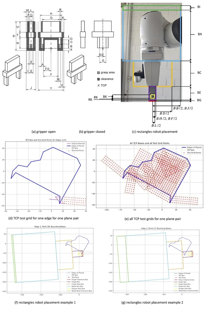
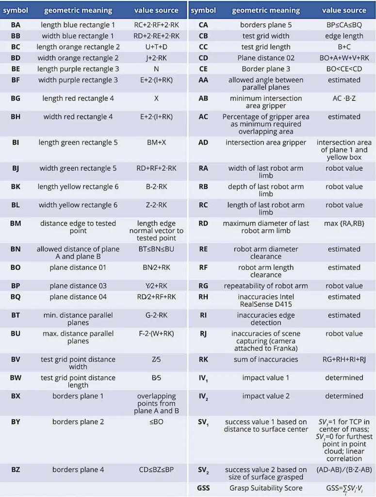
The proposed method is illustrated in Figure 3 as a UML activity diagram and is independent of the technology used. For the sake of simplicity, it is assumed that all end effectors are symmetric and only parallel gripper end effectors are considered for the in-orbit use case where end effectors cannot be applied due to the missing air vacuum suction. For end effectors with unsymmetric geometry, calculations are based on the parameter values that produce the most unfavorable (worst-case) effects, ensuring the highest degree of safety in the approach. Figure 1 depicts the parameters and Figure 2 showcases their correlations. The values used for the parameters for the implementation are available in the GitHub repository [15].
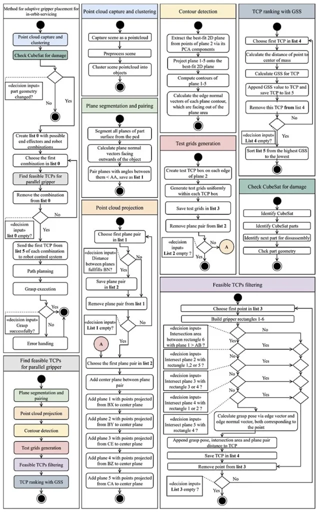
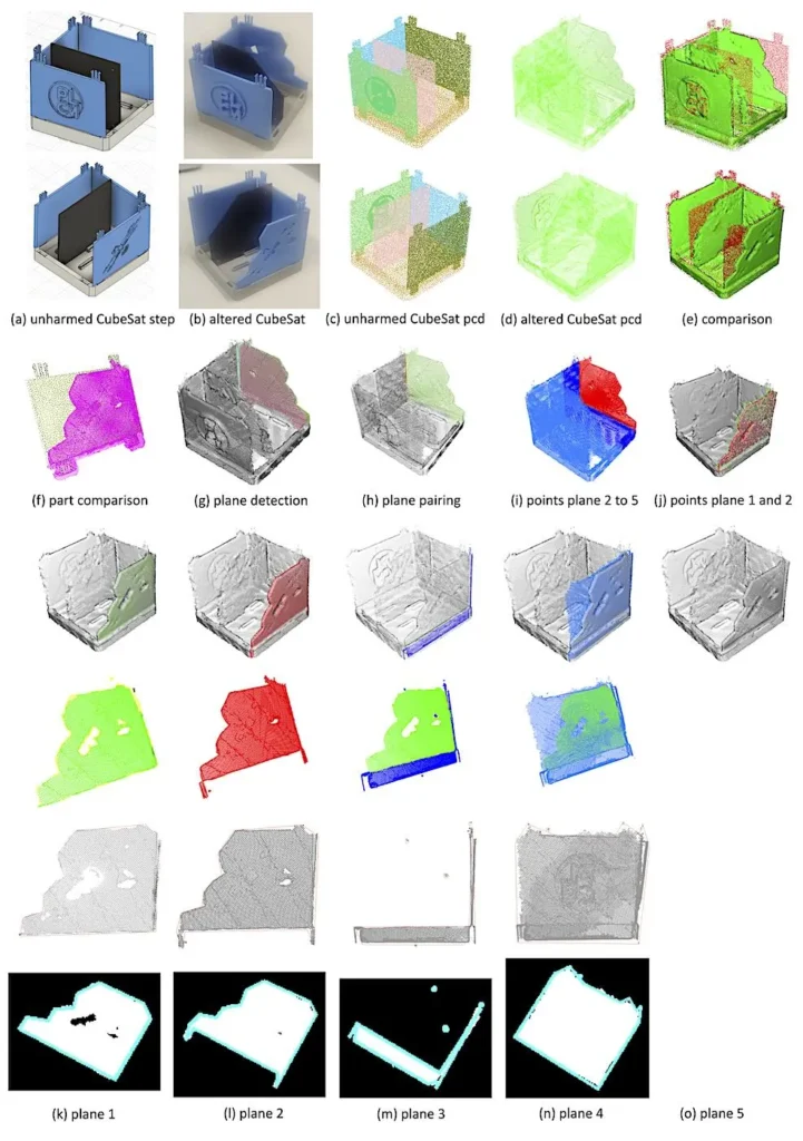
Initially, a defective CubeSat and its environs are captured from multiple angles employing 3D point clouds. To accomplish this, a 3D camera could be attached to a robot arm or multiple cameras could be used. These generated point clouds are subjected to a series of preprocessing steps, which include the removal of points outside the camera’s range. Subsequently, the individual point clouds are unified into a single point cloud. The individual points of the background and the CubeSats are then sorted into individual clusters (Fig. 4d).
The point cloud of the CubeSat is compared with a 3D model database to determine the CubeSat type (Fig. 4e). The individual components of the CubeSat assembly are then identified and positioned on the point cloud (Fig. 4c). The next component of the CubeSat to be disassembled is selected from the sequence planning and is compared to the point cloud to determine whether there has been a significant change in its geometry (Fig. 4f). Once the geometry changes—for instance, due to a collision with space debris—a new gripping position needs to be determined.
Subsequently, combinations of available robots and end effectors are created that use their parameters for further calculations. All available combinations will be used for the Grasp position estimations. Initially, all points of a part are grouped into clusters according to their affiliation to a planar surface geometry (Fig. 4g). The point groups are then assigned to pairs with other planar surfaces that are oriented parallel (Fig. 4h).
The angle between both pairs needs to be smaller than AA, and their normal vectors must face away from each other. If the planes also meet the BN requirement, they can be used as gripping surfaces. Furthermore, the gripping positions are also referred to as tool center points (TCPs). The points in surface A and B will be projected to plane 1 (Fig. 4k), which is in the symmetric center of plane A and B and contains the intersection areas of both surface points projected on the plane.
In the absence of intersection, the creation of a center surface and of the planes 2 to 5 is impeded. Subsequently, an additional plane “plane 2” (Fig. 4l) is generated, encompassing all points with a distance in BY in both positive and negative directions from the center plane. A third plane, “plane 3” (Fig. 4m), contains all points with a distance in CE. Plane 4 (Fig. 4n) contains all points with a distance in BZ and plane 5 (Fig. 4o) all points in a distance in CA. To facilitate the subsequent calculations, edge detection is employed to generate one or more areas per plane from the individual points for all four surfaces. All five planes lie on plane 1 with their plane’s normal vectors’ direction aligned (Fig. 4j).
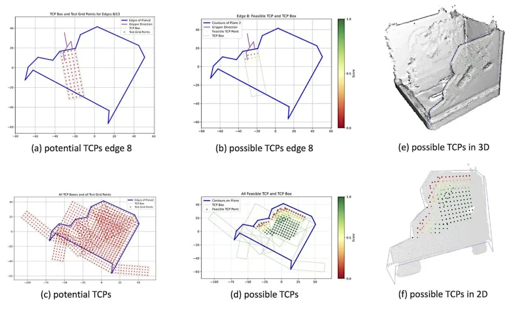
The determination of potential TCPs is predicated on the use of plane 2. The vector for each edge of the area pointing out of the area is identified by checking whether an infinitely long normal vector in the plane of the area intersects an even or odd number of edges (even = outward direction; odd = inward direction). The generation of a rectangle is initiated from each edge in the negative vector direction (Fig. 1d and 1e). The width of the rectangle, designated as CB, is equivalent to the edge length, while its position is determined by the edge’s location. The length of the rectangle is CC.
Then, a test grid of potential TCPs is positioned within this rectangle, with a point spacing configuration in width BV and depth BW. This ensures that the entirety of the rectangle is filled symmetrically from the central point. The X, Y, and Z positions of the TCPs are determined by the position of the point in Cartesian space, and the rotation is defined by the direction of the negative normal vector of the edge and the parallelism of the gripping surfaces to the symmetry plane. For each potential TCP, a combination of rectangles is placed to represent the individual components of the gripper and robot (Fig. 1f and Figure 1g). These are subjected to a collision check with planes 1 to 5. All remaining points are suitable TCPs.
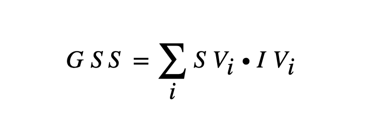
A rank function (1), referred to below as the Grasp Suitability Score (GSS), is used to determine the optimal gripping point from all possible gripping points in accordance with [14].
(1)
This is achieved by weighing the Success Values (SV) with a corresponding Impact Values (IV) where SV1 is correlated to the distance from the TCP to the object’s center of gravity and SV2 is correlated to the size of the overlap area between the gripper finger and the object surface. Each point is assigned a GSS from 0 to 1, with a higher value indicating a better suitability of the gripping point (Fig. 5). The TCP with the highest GSS value is forwarded to the robot controller and replaces the original gripping position. All TCPs of the disassembly skill are adjusted by the offset to the original gripping point. An additional collision check is required to prevent collisions during movement in the skill, since only the gripping position of the end effector is considered during the method. Subsequently, the component gripping procedure is executed.
Evaluation and discussion of the adaptive gripper placement
To evaluate the adaptive gripper placement method, a simplified CubeSat assembly is employed. The evaluation is conducted by a Franka Research 3 robot arm with a Franka parallel gripper. Figure 4a depicts the unharmed CubeSat and Figure 4b the damaged one used for the evaluation. The CubeSat was captured with an Artec Eva 3D scanner. Figure 4c to Figure 4o depict the images created by the implementation which proves the functionality of the developed method for the adaptive gripper placement. A half-disassembled CubeSat is used because it better showcases the collision checks in the process of the grasp TCP estimation and the used end effector cannot grasp a closed CubeSat due to the maximum gripper distance of 80mm compared to a CubeSat with a size of roughly 100*100*100mm3.
All possible TCPs are shown with a heatmap of their GSS values green=1 and red=0 in Figure 5. The software’s total runtime for different use cases was roughly between 0.5 and 5 minutes depending on the part complexity and point cloud density. However, there has been no effort to optimize the code’s runtime, and this time is reasonable considering the number of satellites currently in space that need in-orbit servicing. The code written for the implementation, the 3D files and results are available at GitHub [15].
The current limitations of the implementation are that only planar surfaces for grasp estimation are used, which is no problem because the grasping of non-planar surfaces could lead to insecure gripping. That poses a high risk in an in-orbit factory due to unpredictable movements and damage from insecurely grasped and oriented parts in an end effector which could be released during a robot movement or could collide with the environment. The current method is only applicable for parallel gripper end effectors which can be assumed to the parameters of the end effector geometry in Figure 1. That concludes most of the industry relevant end effector types excluding vacuum suction cup end effectors which are not viable for an airless in-orbit factory. Due to the size and orientation of the test grids, not all possible grasping positions will be tested.
This means that the optimal position may not be found, but that is not a problem because grasping requires only one viable position with a high enough chance of success. The approach presented here is the first step in overcoming the problem of components deviating during the servicing of an in-orbit factory. As previously mentioned, this approach must now be expanded to include additional end effector types to enable flexibility and support more complex operations, such as screwing. Furthermore, the next step should be to investigate the use and data exchange with digital twins of the products. These could be an ideal basis for providing 3D models. Additionally, the virtual representation of the physical condition via the digital twin could support the process by providing further information, for example, in the event of already known damaged parts.
Summary and outlook for adaptive gripper placement for in-orbit servicing
Due to the increasing number of in-orbit satellites and their inevitable end of life, a method for in-orbit satellite servicing was presented. The proposed method can achieve adaptive gripper placement of altered components for in-orbit servicing, and it moreover archives a grasp TCP estimation for unknown parts. Both parts of the method can be used separately from each other in a modularized system. The grasp position estimation could be changed to an already proven grasp estimation algorithm, or the developed method could be advanced to consider more complex end effector geometries. The method uses rule-based grasp estimation and Grasp Suitability Score calculations which are suitable for use in an in-orbit servicing factory.
The only black box systems are machine learning-based edge detections and point cloud postprocessing, which use established algorithms but are prone to error. The method is independent of the technologies used and can be fully automized, requiring no human interaction during the repair process. In future steps, a sequence, path and trajectory planning for the in-orbit servicing as well as a digital process twin could be included in the method to achieve a fully automized flexible in-orbit servicing of CubeSats. The RISE mission, presented by the European Space Agency, exemplifies the potential applications and significance of this approach, as it is now launching a satellite equipped with robotic arms for in-orbit servicing [16].
This article was published jointly as part of the AI2SB, ACOR and RoboTeach projects. AI2SB is funded by the DFG and CAPES under grant numbers 547432938 (DFG) and 88881.964206/2024-01 (CAPES). ACOR was funded by the BMWK under project number 50RP2240A-C and RoboTeach is funded by the BMWK as a ZIM project under grant number 16KN096034.
This is an original article. The German translation can be accessed via DOI: 10.30844/I4SD.25.6.10
Bibliography
[1] De Gaudenzi, R.: Satellite networks: Past Present and Future Challenges – Part 2: Broadband Systems. In: IEEE Aerosp. Electron. Syst. Mag. (2025), pp. 1–9. DOI: 10.1109/MAES.2025.3565491.[2] European Space Agency: ESA’S ANNUAL SPACE ENVIRONMENT REPORT. URL: https://www.sdo.esoc.esa.int/environment_report/Space_Environment_Report_latest.pdf, accessed: 11.08.2025.
[3] Leutert, F. et al.: AI-enabled Cyber–Physical In-Orbit Factory – AI approaches based on digital twin technology for robotic small satellite production. In: Acta Astronautica 217 (2024), pp. 1–17. DOI: 10.1016/j.actaastro.2024.01.019.
[4] Opromolla, R. et al.: Future in-orbit servicing operations in the space traffic management context. In: Acta Astronautica 220 (2024), pp. 469–477. DOI: 10.1016/j.actaastro.2024.05.007.
[5] Mühlbauer, M. et al.: AI-based Robust and Failure-Tolerant Processes for In-Orbit Manufacturing of Modular Small Satellites. 2024. URL: https://mediatum.ub.tum.de/node?id=1755632
[6] Steinmetz, F. J.: Intuitive robot programming for novice and expert user. In: RWTH Aachen University (2022). DOI: 10.18154/RWTH-2022-08236.
[7] George, P.; Cheng, C.-T. et al.: Task Complexity and the Skills Dilemma in the Programming and Control of Collaborative Robots for Manufacturing. In: Applied Sciences 13 (2023) 7, p. 4635. DOI: 10.3390/app13074635.
[8] Trautner, T.; Ayatollahi, I. et al.: Behavioral modeling of manufacturing skills in OPC UA for automated execution by an independent cell controller. In: Procedia CIRP 99 (2021), pp. 633–638. DOI: 10.1016/j.procir.2021.03.085.
[9] Parigi Polverini, M.; Zanchettin, A. M.; Rocco, P.: A constraint-based programming approach for robotic assembly skills implementation. In: Robotics and Computer-Integrated Manufacturing 59 (2019), pp. 69–81. DOI: 10.1016/j.rcim.2019.03.005.
[10] Du, G.; Wang, K. et al.: Vision-based robotic grasping from object localization, object pose estimation to grasp estimation for parallel grippers: a review. In: Artif Intell Rev 54 (2021) 3, pp. 1677–1734. DOI: 10.1007/s10462-020-09888-5.
[11] Ma, H.; Wang, G. et al.: Robotic grasping method with 6D pose estimation and point cloud fusion. In: Int J Adv Manuf Technol 134 (2024) 11–12, pp. 5603–5613. DOI: 10.1007/s00170-024-14372-3.
[12] Bekiroglu, Y. et al.: Benchmarking Protocol for Grasp Planning Algorithms. In: IEEE Robot. Autom. Lett. 5 (2020) 2, pp. 315–322. DOI: 10.1109/LRA.2019.2956411.
[13] Zapata-Impata, B. S.; Gil, P. et al.: Fast geometry-based computation of grasping points on three-dimensional point clouds. In: International Journal of Advanced Robotic Systems 16 (2019) 1. DOI: 10.1177/1729881419831846.
[14] Rein, J.; Voges, J.; Reuther, A.; Schleich, B.: Method for determining the most suitable grasp tcp for robot part handling. In: Srihari, K.; Khasawneh, M. T.; Yoon, S.; Won, D. (eds): Flexible Automation and Intelligent Manufacturing: The Future of Automation and Manufacturing: Intelligence, Agility, and Sustainability, Lecture Notes in Mechanical Engineering. Cham 2026, pp. 347–354. DOI: 10.1007/978-3-032-07675-5_33.
[15] Rein, J.: Adaptive-in-Orbit-Servicing-of-Altered-Satellite-Components. GitHub. 2025. URL: https://github.com/JustusRein/Adaptive-In-Orbit-Servicing-of-Altered-Satellite-Components. DOI: 10.5281/zenodo.16947439.
[16] European Space Agency, in-orbit servicing mission RISE. [Online]. URL: https://www.esa.int/Space_Safety/ESA_to_build_first_in-orbit_servicing_mission_with_D-Orbit, accessed: 03.11.2025.
Your downloads
Potentials: Innovation
Solutions: Logistics Maintenance
You might also be interested in