Modeling Influences on the Wire Arc Additive Manufacturing Process |
| Journal | Industrie 4.0 Management |
| Issue | Volume 39, 2023, Edition 5, |
| Open Access | https://doi.org/10.30844/I4SE.23.1.80 |
| Bibliography | Share | Cite | Download |
Abstract
Keywords
Article
The aim of the article is to depict the process and information flows and to show possible interactions between the manufacturing parameters. This allows the entire process to be clearly mapped out and influences to be analyzed in a structured manner. In the WAAM process, the lack of process stability means that optimal component quality is not already a given at the production planning stage. The information provided here is intended to give an overview of the relevant influences in order to optimize planning and component quality.
For this purpose, the Structured Analysis and Design Technique, or SADT method, is used.
The SADT method
The SADT method originates from the field of software development, is easy to understand and clearly describes an information flow. The basic notation form consists of a box-arrow diagram, which is shown in Figure 1 [5].
The central “Function” box is surrounded by three input arrows and one output arrow. The “Function” box describes an activity or process step that converts inputs into outputs.
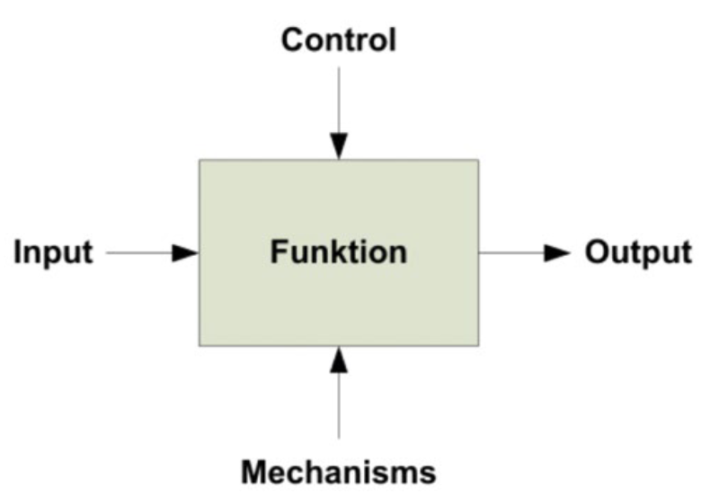
The “Input” arrow located on the left side of the activity box shows the type of data that should be available for processing. On the right side of the activity box is the “Output” arrow, which is the only one pointing outwards. This describes the results of the conversion process. The “Control” arrow entering the box from the top side is defined as any type of constraint that manipulates the outcome of the function in any way. The last arrow of the diagram is the “Mechanisms” arrow. This enters the activity box from the bottom and describes the tools, resources, or people that are required to be able to perform the central function [5].
Modeling the WAAM process
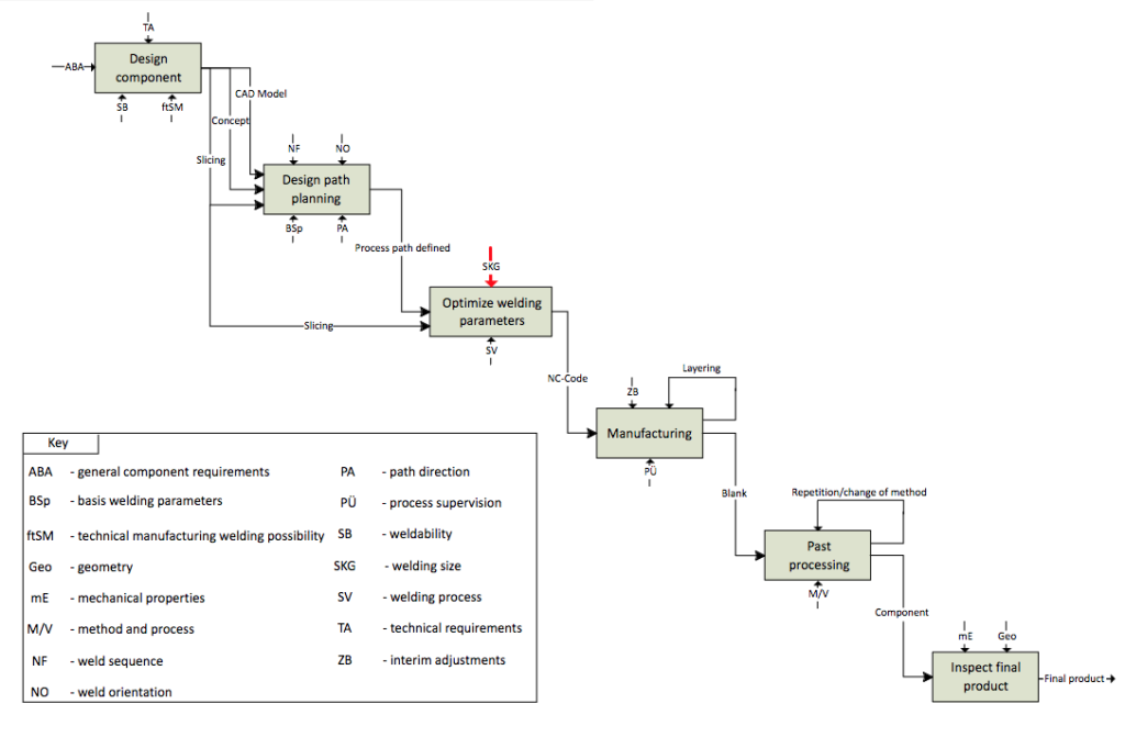
In this article, the manufacturing process of the WAAM method is divided into eight process steps: Planning, CAD model creation, slicing, path planning, robot code configuration, weld parameter configuration, manufacturing and reworking [6]. For a model that corresponds to the SADT method, these steps have been reduced to six distinct functions, which are shown in Figure 2.
In the first activity, the focus is on determining the general component design. Subsequently, the path planning must be designed and the welding parameters must be chosen accordingly. Once these fundamentals have been established, the component is manufactured and, if necessary, reworked. The final activity is the potential inspection of the final product.
Design component
The component design is derived from the general component requirements. Properties such as intended use, geometry and material must be defined before the actual planning stage commences. Once design is complete, the manufacturing process can be started [2].
Component design is controlled by the technical requirements. These consist of the base plate layer, the resulting microstructure and component safety [2].
The base plate layer describes how the base plate, on which the component is built, will be integrated into the component being manufactured. There are various approaches that influence the manufacturing process with regard to the type of component arrangement. Several possible variants are shown in Figure 3 [2].
The integration, for example as an outer or inner wall, depends on the systems technology used and on its degrees of freedom. The selection of the optimum base plate position can be determined on the basis of five evaluation criteria. These are: Material surplus, disposition volume, number of layers, complexity of integration and symmetry. The respective weighting of the individual criteria depends on the system technology used [2, 7].
The microstructure of a WAAM component tends to lack homogeneity due to the manufacturing process [8]. The lower layers are exposed to multiple heat inputs and are therefore finer than the upper layers. This increasing grain growth may lead to a loss of strength with increasing component height [2].
The fulfillment of a function within a defined service life is the central requirement for a component. Large-volume components with high wall thicknesses and simple structures are particularly suitable for the WAAM process. The strength values can deviate from the manufacturer’s specifications due to repeated over-welding. It is therefore advisable to create test specimens and check them for their material properties.
Furthermore, attention should be paid to the ratio of component surface area to component volume. Smaller surfaces dissipate heat more slowly, which can result in negative effects, such as an excessively high temperature between component layers, greater residual stress, and component warpage. One way to reduce residual stress is to design the component symmetrically. Rotational or mirror-symmetrical structures allow for better stress compensation and improve a component’s dimensional stability and mechanical properties. This principle also works for geometries that are not completely symmetrical [2].

Weldability and the manufacturing-level technical welding possibility are two mechanisms that are important for performing the activity of component design [2, 9].
According to the ISO/TR 581, the weldability of a metallic material also depends on weld applicability, safety and possibility.
All these requirements are determined by the material used, the design, and the manufacturing process [9].
For the WAAM process, articulated, or delta, robots are primarily used, but also machining centers, leading to specific restrictions for manufacturing processes. Furthermore, the machining head in question must be taken into account. This can be equipped with additional systems, such as sensors, a wire reservoir or a cooling system. The resulting influence on the component design must be considered [2].
The output factors of the initial function of Figure 2 are, in addition to the basic concept, the CAD and the layer model of the component. The layer model is created by a process known as slicing. This divides the 3D geometry into layers, each with a predefined height [10].
Design path planning
The output factors of the previous activity are used as inputs for the “Design path planning” process step. They are therefore a mandatory prerequisite for the conversion process [5].
Limitations of this activity are the weld sequence and the weld orientation. When planning the weld sequence, care must be taken to avoid sharp-edged corners, as these can lead to unevenly shaped components [2]. Alternatively, an overlapping joint can be produced, which is then removed in the reworking process. Furthermore, geometrical deviations can occur at the start and end of a weld. Long and evenly wide welds should be produced in one step.
If this is not possible, it is advisable to select an application direction that alternates layer by layer, thus keeping deviation as low as possible [2]. The correct choice of time and temperature between individual layers is important for microstructure formation [11].
The weld orientation describes the alignment of the manufactured component with respect to the welding direction. Weld orientation has an influence on the load-bearing capacity of the component. Prior literature in this area indicates that a 45° orientation is considered to be the most resilient [12].
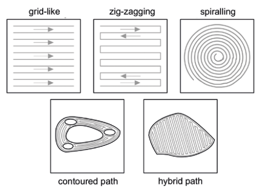
Selection of the path characteristic supports path planning. Characteristics for this are visualized in Figure 4.
These path direction choices have different advantages and disadvantages and can also be used in combination [13]. Furthermore, initial assumptions about optimal welding parameters are made in this process step. These are of significant importance for the final result and thus have to be considered from the beginning of the process [6].
The result of the conversion process is a clearly defined process path that leads to creation of the component. Based on this, the next step, which is optimization of the welding parameters, can be started within the process [5].
Optimize welding parameters
The input factor for the “Optimize welding parameters” function is the result of the previous process step. The parameters must be determined with consideration for the process path. The layer model that has already been generated also needs to be taken into account here, as it forms the basis on which the welding parameters are then optimized [5].
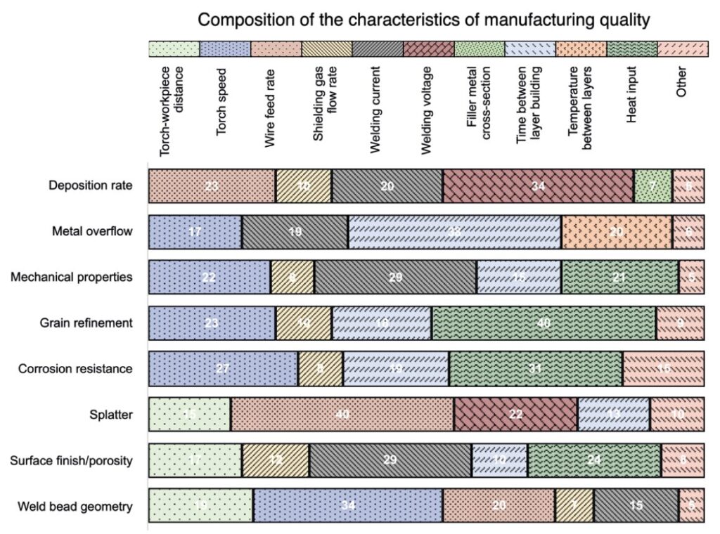
Controlling influences exerted on the parameters include the following: Distance between torch and workpiece, torch speed, wire feed rate, gas metal arc welding flow rate, welding current, voltage, filler metal cross-section, time and temperature between layers, and heat input. These contribute decisively to the creation of stable and defect-free components and are thus marked with a red arrow in the SADT model. Figure 5 shows the respective relationship of the parameters to the characteristics of the manufacturing quality [14].
The figure is based on the analyzed welding parameters of Pattanayak and Sahoo [14], who related them to the resulting manufacturing quality characteristics in percentage terms. Weld bead geometry, deposition rate, metal overflow, surface finish or porosity, spatter, grain refinement, corrosion resistance and mechanical properties were considered. The diagram visualizes the different relationships that play into the characteristics of the manufacturing quality. For each quality characteristic, four to five of the most important welding parameters are listed and the respective percentage of influence is indicated for each. Parameters which have an insignificant effect are marked as “Other.”
According to Pattanayak and Sahoo, the parameters of torch speed, heat input, time between layers and welding current have an influence across all characteristics and are of particular importance. They have significant effects on mechanical properties, grain refinement, and corrosion resistance. Following these, the control variables that have the next greatest overall influence according to Pattanayak and Sahoo are distance between the torch and the workpiece, wire feed rate, shielding gas flow rate, and welding voltage. Despite having a smaller overall effect on manufacturing characteristics, these are still relevant. The parameters of filler metal cross-section and temperature between layers affect both deposition rate and metal overflow [14].
Another important parameter not represented in Figure 5 is the composition of protective gases. A distinction is made here between active and inert gases. In contrast to inert gases, active gases create a chemical reaction upon contact with the metal. Basically, the gas serves to shield the molten bath from external influences. Argon, helium and carbon dioxide are frequently used as gases. Depending on the applications, mixed gases can be used [15].
The welding process used is of importance for the parameter determination. In principle, any arc welding process can be used for the WAAM process, the most common one being gas metal arc welding, tungsten inert gas welding, or plasma arc welding. The result of the parameter determination is the finished NC code [15].
Manufacturing
The finished NC code is the input factor for the “Manufacturing” function. It contains the process path and the defined welding parameters. Manufacturing can be started on the basis of this code [5].
Control elements of this activity consist of a variety of possible intermediate processing steps and repeated layer application. Examples of intermediate processing steps include interpass rolling, milling, and cooling. In interpass rolling, a rolling process occurs after a defined number of layers, which refines the microstructure by plastic deformation and improves its mechanical properties [16]. Furthermore, interpass cooling can be used. In this case, active cooling of the last deposited layer occurs during production. Consequently, the interlayer temperature is more effectively controlled [16]. Interpass milling serves to reduce the weld bead to a predefined height. Consequently, the accumulation of defective deposition heights is reduced [17].
The individual layers that are applied can be seen as intermediate results and can enter the conversion process again as a control element. This makes it possible to influence the manufacturing process after the application of each layer.
During the manufacturing process, the parameters of the environment as well as the heat conduction change continuously due to the layer-by-layer material application. Potential errors can add up throughout the process and thus require monitoring. This control is carried out via comparison of the target and actual product. The high process temperature [19], however, makes it difficult to measure actual values.
The final result of the conversion process is the finished blank, which needs to be reworked due to manufacturing variations accrued during the process [2].
Post processing
The input variable for reworking is the finished blank. Given the standard manufacturing variation of one to three millimeters, post processing – or reworking – is usually necessary [2].
The control element of the reworking function is the preceding output of the prior conversion process step, as seen during manufacturing step. Reworking can be conducted using several methods, or by applying one method repeatedly [16].
Several processes can be used for component reworking. Cutting rework is the most commonly used of these. Implementing a reworking process makes it possible to improve the mechanical properties of components [2]. Methods such as peening, which is understood as mechanical hammering on the component, or ultrasonic treatment can improve the surface properties as well as component microstructure. The latter method is not suitable for large or complex components [16].
The output of this function is the finished component. In the final process step, if deemed necessary, this final product can be checked for mechanical properties [5].
Inspect final product (if necessary)
The last function on the SADT model is the inspection of the final product, should this be necessary. The input factor of this is the finished component, which exhibits certain mechanical properties and a previously defined geometry. In the case of destructive testing, VDI 3405-2 recommends that additional test specimens are manufactured within the same manufacturing process. Furthermore, the VDI guideline gives recommendations for additional material tests [19].
Conclusion
In this article, the WAAM manufacturing process and its influencing variables have been presented. The SADT method was used to better facilitate this. The various influencing parameters across the manufacturing process were shown. Welding parameters in particular were considered in detail as the main influencing factors and possible interactions were shown. These factors and interactions offer the greatest possibility of influencing the process. The model does not claim to be comprehensive, but it does provide significant assistance for improving component quality. The visualization method used is a common approach for representing complex interrelationships in computer-aided manufacturing.
Bibliography
[1] DIN EN ISO/ASTM 52900: Additive Fertigung – Grundlagen – Technologie (ISO/ASTM DIS 529000:2018-7), DIN Deutsches Institut für Normung e.V., Berlin.[2] Schmid, C.: Konstruktive Randbedingungen bei Anwendung des WAAM-Verfahrens. In: Lachmayer, R.; Rettschlag, K.; Kaierle, S. (ed): Konstruktion für die Additive Fertigung. Berlin Heidelberg 2020.
[3] Lachmayer, R.; Lippert, R. B.: Entwicklungsmethodik für die Additive Fertigung. Berlin Heidelberg 2020
[4] Chunyang, X.; Zengxi P. et al.: A review on wire arc additive manufacturing: Monitoring, control and a framework of automated system. In: Journal of Manufacturing Systems, p. 1.
[5] Tolk, A.; Diallo, S. Y. et al.: Effective and scalable uncertainty evaluation for large-scale complex system applications. In: 2014 Winter Simulation Conference.
[6] Singh, S. R.; Khanna, P.: Wire arc additive manufacturing (WAAM): A new process to shape engineering materials. In: Materials Today 44 (2021): Proceedings, pp. 118-128.
[7] Lockett, H.; Ding, J. et al.: Design for Wire + Arc Additive Manufacture: design rules and build orientation selection. In: Journal of Engineering Design 28 (2017) 7-9, pp. 568-598.
[8] Jin, W.; Zhang, C. et al.: Wire Arc Additive Manufacturing of Stainless Steels: A Review. In: Applied Sciences 10 (2020) 5, p. 1563.
[9] DIN-Fachbericht ISO/TR 581: Schweißbarkeit – Metallische Werkstoffe – Allgemeine Grundlagen; Deutsche Fassung ISO/ TR 581:2005, DIN Deutsches Institut für Normung e.V., Berlin.
[10] Huang, J.; Qin, Q. et al.: A dynamic slicing algorithm for conformal additive manufacturing. In: Additive Manufacturing Vol. 51 (2022).
[11] Xiong, Y.; Wen, D. et al.: Effect of interlayer temperature on microstructure evolution and mechanical performance of wire arc additive manufactured 300M steel. In: Materials Science and Engineering: A, 831 (2021).
[12] Kyvelou, P. et al.: Mechanical and microstructural testing of wire and arc additively manufactured sheet material. In: Materials & Design 192 (2020), pp. 108675.
[13] Singh, S.; Sharma, S. et al.: A review on process planning strategies and challenges of WAAM. In: Materials Today: Proceedings 47 (2021), pp. 6564-6575.
[14] Pattanayak, S.; Sahoo, S.: Gas metal arc welding based additive manufacturing—a review. In: CIRP Journal of Manufacturing Science and Technology 33 (2021).
[15] Schuler, V.; Twrdek, J.: Praxiswissen Schweißtechnik, 6th edition. Wiesbaden 2019.
[16] Gibson, I.; Rosen, D.; Stucker, B.; Khorasani, M.: Additive Manufacturing Technologies, 3th edition. Cham 2021.
[17] Lachmayer, R.; Lippert, R. et al.: Additive Serienfertigung. Berlin 2018.
[18] Richter, A.; Scheck, M. et al.: Erfassung der Schmelzbadfläche mit Korrektur der Perspektive zur Prozessregelung eines Wire and Arc Additive Manufacturing, In: tm – Technisches Messen 89 (2022) 7-8, pp. 525-533.
[19] VDI-3405: Blatt 2 Additive Fertigungsverfahren Strahlschmelzen metallischer Bauteile Qualifizierung, Qualitätssicherung und Nachbearbeitung, Verein Deutscher Ingenieure e.V. Berlin (Fall 2013).